
Computer,
Videospiele, Videokameras, Spielcomputer; alles dieses Produkt-Video
gibt Zeichen, dass durch einen Fernseher(Fernsehgerät) gezeigt werden
muß. Wenn der zweifelhafte Fernsehempfänger ein Video nicht hat, geben
ein, und sein(ihr) Inhaber sträubt sich dagegen, es mutwillig zu
zerstören, um denjenigen dann anzupassen, diese Sorte des Modulators ist
die offensichtliche Lösung. Es ist eine einfache Kreislinie, die
Videosignale bearbeitet, ihnen zu ermöglichen, gerade in den Lufteingang
des Fernsehapparates gefüttert zu werden.
Ordinateurs, jeux vidéo, caméras vidéo, ordinateurs de jeux; tous ces signaux de vidéo de produits alimentaires qui doivent être montrés(affichés) via un poste de télévision. Si le téléviseur en question n'a pas d'entrée vidéo et son propriétaire est réticent pour le vandaliser pour adapter celui alors ce tri(sorte) de modulateur est la solution évidente. C'est un circuit simple qui traite des signaux vidéo de leur permettre d'être alimenté tout droit dans l'apport(la saisie) aérien du poste de télévision.
Computadoras, videojuegos, cámaras de vídeo, ordenadores juegos, todas estas señales de vídeo producen que deben ser mostradas a través de un aparato de televisión. Si el receptor de TV en cuestión no tiene una entrada de vídeo y su propietario es reacio a cometer actos de vandalismo con el fin de adaptarse a uno, entonces este tipo de modulador es la solución obvia. Se trata de un circuito simple que procesa señales de vídeo a fin de que puedan ser alimentados directamente a la entrada de antena del aparato de TV.
Computers, video games, video cameras, games computers; all of these produce video signals that must be displayed via a television set. If the TV receiver in question does not have a video input and its owner is reluctant to vandalise it in order to fit one then this sort of modulator is the obvious solution. It is a simple circuit that processes video signals to enable them to be fed straight into the TV set's aerial input.
A 'TV modulador' es realmente no es más que un transmisor. Es un lugar muy pequeño transmisor, es cierto, pero no obstante, que es lo que es. ¿Qué hace un modulador realmente? En general-y este diseño no es la excepción a la regla - es un oscilador simple que genera una frecuencia en algún lugar de la región de VHF o UHF. El oscilador se modula con la señal de vídeo y la onda portadora modulada así generada se alimenta a la entrada de antena del televisor mediante un cable. Entonces todo lo que queda por hacer es sintonizar el televisor en la frecuencia correcta.
Un «modulateur de télévision 'est vraiment pas plus d'un émetteur. Il s'agit d'un très petit émetteur, certes, mais pas moins que c'est ce qu'il est. Qu'est-ce qu'un modulateur réellement faire? En général, et cette conception ne fait pas exception à la règle - c'est un simple oscillateur qui génère une fréquence quelque part dans la région VHF ou UHF. L'oscillateur est modulé par le signal vidéo et l'onde porteuse modulée ainsi généré est introduit dans l'entrée antenne du téléviseur par l'intermédiaire d'un câble. Puis tout ce qui reste à faire est de régler le téléviseur à la bonne fréquence.
A 'TV-Modulator "ist wirklich nicht mehr als ein Sender. Es ist ein sehr kleiner Sender, zugegebenermaßen, aber nichts desto weniger das ist, was es ist. Was macht ein Modulator eigentlich? In der Regel-und dieser Entwurf ist keine Ausnahme von der Regel - es ist ein einfacher Oszillator, der eine Frequenz erzeugt irgendwo im VHF-oder UHF-Bereich. Der Oszillator moduliert wird, mit dem Videosignal und der modulierten Trägerwelle so erzeugt wird, in die TV-Gerätes Antenneneingang zugeführt über ein Kabel. Dann alles, was zu tun bleibt, ist abzustimmen das Fernsehgerät auf die richtige Frequenz.
A 'TV modulator' is really no more than a transmitter. It is a very small transmitter, admittedly, but none the less that is what it is. What does a modulator actually do? In general -and this design is no exception to the rule - it is a simple oscillator that generates a frequency somewhere in the VHF or UHF region. The oscillator is modulated with the video signal and the modulated carrier wave thus generated is fed into the TV set's aerial input via a cable. Then all that remains to do is tune the TV to the correct frequency.
Set the TV receiver to maximum brightness and contrast.
Feed a video signal into the modulator (a video recording of a test card, or a link to a computer's 'TV' socket, could be used) and connect the circuit's output to the TV's aerial input.
Set P2 to mid-position and P1 to minimum resistance (fully anti clockwise).
Tune the TV receiver to a harmonic, preferably one of the VHF bands (channels 2. . .12). The tuning is correct when the 'snow' on the screen disappears and/or the screen becomes dark.
Turn P1 very slightly until 'something' becomes visible.
Calibrate P2 to give the best possible quality image. If the result is not very
good the wiper of Pl can be moved a bit more and P2 again trimmed to give a better image.
If this still fails to provide an acceptable result tune the TV to the next harmonic.
This must give a decent image.
Ordinateurs, jeux vidéo, caméras vidéo, ordinateurs de jeux; tous ces signaux de vidéo de produits alimentaires qui doivent être montrés(affichés) via un poste de télévision. Si le téléviseur en question n'a pas d'entrée vidéo et son propriétaire est réticent pour le vandaliser pour adapter celui alors ce tri(sorte) de modulateur est la solution évidente. C'est un circuit simple qui traite des signaux vidéo de leur permettre d'être alimenté tout droit dans l'apport(la saisie) aérien du poste de télévision.
Computadoras, videojuegos, cámaras de vídeo, ordenadores juegos, todas estas señales de vídeo producen que deben ser mostradas a través de un aparato de televisión. Si el receptor de TV en cuestión no tiene una entrada de vídeo y su propietario es reacio a cometer actos de vandalismo con el fin de adaptarse a uno, entonces este tipo de modulador es la solución obvia. Se trata de un circuito simple que procesa señales de vídeo a fin de que puedan ser alimentados directamente a la entrada de antena del aparato de TV.
أجهزة الكمبيوتر، وألعاب الفيديو، وكاميرات الفيديو، وألعاب الكمبيوتر، وكل هذه إشارات الفيديو المنتجات التي يجب أن يتم عرضها عبر جهاز التلفزيون. إذا لم يكن لدى المتلقي التلفزيون في سؤال لأحد إدخال الفيديو وصاحبها غير راغبة في تخريب ذلك من أجل احتواء واحد ثم هذا النوع من المغير هو الحل واضح. بل هو دائرة بسيطة الذي يعالج إشارات الفيديو لتمكينهم من أن تغذى مباشرة إلى.مدخلات الجوي مجموعة التلفزيون
Computers, video games, video cameras, games computers; all of these produce video signals that must be displayed via a television set. If the TV receiver in question does not have a video input and its owner is reluctant to vandalise it in order to fit one then this sort of modulator is the obvious solution. It is a simple circuit that processes video signals to enable them to be fed straight into the TV set's aerial input.
A 'TV modulador' es realmente no es más que un transmisor. Es un lugar muy pequeño transmisor, es cierto, pero no obstante, que es lo que es. ¿Qué hace un modulador realmente? En general-y este diseño no es la excepción a la regla - es un oscilador simple que genera una frecuencia en algún lugar de la región de VHF o UHF. El oscilador se modula con la señal de vídeo y la onda portadora modulada así generada se alimenta a la entrada de antena del televisor mediante un cable. Entonces todo lo que queda por hacer es sintonizar el televisor en la frecuencia correcta.
Un «modulateur de télévision 'est vraiment pas plus d'un émetteur. Il s'agit d'un très petit émetteur, certes, mais pas moins que c'est ce qu'il est. Qu'est-ce qu'un modulateur réellement faire? En général, et cette conception ne fait pas exception à la règle - c'est un simple oscillateur qui génère une fréquence quelque part dans la région VHF ou UHF. L'oscillateur est modulé par le signal vidéo et l'onde porteuse modulée ainsi généré est introduit dans l'entrée antenne du téléviseur par l'intermédiaire d'un câble. Puis tout ce qui reste à faire est de régler le téléviseur à la bonne fréquence.
A 'TV-Modulator "ist wirklich nicht mehr als ein Sender. Es ist ein sehr kleiner Sender, zugegebenermaßen, aber nichts desto weniger das ist, was es ist. Was macht ein Modulator eigentlich? In der Regel-und dieser Entwurf ist keine Ausnahme von der Regel - es ist ein einfacher Oszillator, der eine Frequenz erzeugt irgendwo im VHF-oder UHF-Bereich. Der Oszillator moduliert wird, mit dem Videosignal und der modulierten Trägerwelle so erzeugt wird, in die TV-Gerätes Antenneneingang zugeführt über ein Kabel. Dann alles, was zu tun bleibt, ist abzustimmen das Fernsehgerät auf die richtige Frequenz.
A 'TV modulator' is really no more than a transmitter. It is a very small transmitter, admittedly, but none the less that is what it is. What does a modulator actually do? In general -and this design is no exception to the rule - it is a simple oscillator that generates a frequency somewhere in the VHF or UHF region. The oscillator is modulated with the video signal and the modulated carrier wave thus generated is fed into the TV set's aerial input via a cable. Then all that remains to do is tune the TV to the correct frequency.
 |
A 'TV modulator' is really no more than a transmitter. It is a very small transmitter, admittedly, but none the less that is what it is. What does a modulator actually do? In general -and this design is no exception to the rule - it is a simple oscillator that generates a frequency somewhere in the VHF or UHF region. The oscillator is modulated with the video signal and the modulated carrier wave thus generated is fed into the TV set's aerial input via a cable. Then all that remains to do is tune the TV to the correct frequency |
The layout
The whole business is not quite as simple as we have just suggested, of course, as the mini transmitter must meet certain requirements. The frequency stability must be very good as, indeed, must the quality of the display. The required frequency stability is achieved by the use of a crystal oscillator. A well thought out choice of component values takes care of the display quality: the modulator allows a resolution of 80 characters per line, as this is a value that is often needed. A very important feature of the circuit that must be decided is the transmission frequency. If this is only a single channel, as suggested above, h gives rise to some practical problems. Different users will want different channels, the carrier wave can become somewhat difficult to locate, and unless the frequency is exactly spot on no signal will be received. A much better idea is to ensure that the HF signal contains a large number of different frequencies. This makes it much easier to tune the TV set to one of the frequencies as there will surely be one to suit every user.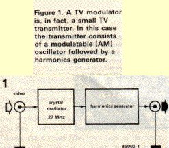 |
The block diagram of figure I shows how this is achieved. The TV modulator is made up of two parts, namely a modulatable crystal oscillator and a harmonics generator. The oscillator operates at a frequency of 27 MHz, which is quite low so inexpensive crystals are readily available. The harmonics generator converts the oscillator signal into a sort of frequency spectrum containing all the multiples of 27 MHz up to about 1800 MHz. The TV modulator's output signal is made up of a large number of little peaks, each of which is a complete transmitter signal. At least one of these will always be in band I (VHF channels 2. . . 4), one in band III (VHF channels S. . .12) and many of them will be in bands IV and V (UHF channels 21.. .69). |
The circuit diagram
Like the block diagram, the circuit (shown in figure 2) is very straightforward. The crystal oscillator is based on a very fast HF transistor, Tl (BFR91), which performs the amplitude modulation. Apart from this there is little to be said about the oscillator except, perhaps, that it is essential to use the correct values for the components surrounding Tl. This is, of course, simply common sense in this sort of HF circuit. The harmonics generator is formed by two Schottky diodes, Dl and D2. These diodes must switch very quickly in time with the 27 MHz signal so they provide strong harmonics up into the gigahertz range. The modulation depth can be set with Pl, while the oscillator's d.c. value can be varied by means of P2. The combination of these two presets enables either positive or negative amplitude modulation to be selected. This is essential as the harmonics produced vary in this respect. We will discuss the calibration of Pl and P2 later in this article. The power for the circuit can be provided by either an unstabilized 8...30 V or a stabilized 5 V. The latter could be taken from a computer's power supply and in this case ICI is not needed.Construction
The tiny printed circuit board designed for this circuit is shown in figure 3. It is not double-sided as this was found to be unnecessary. Construction is thereby simplified and readers who do not buy the board through our EPS service (tut-tut) will find it easier to make themselves. Building the circuit is simply a matter of fitting the components onto the printed circuit board. The coils, often a source of much teeth-gnashing and hair-pulling, will not be a problem in this case. Two of them, Ll and L2, are made by winding 3.5 turns of enamelled copper wire (about 0.2 mm thick) on a 3.5 mm ferrite bead. Another, L4, is just one turn of copper wire (0.8. . . 1 mm thick) air-wound with a diameter of 8 mm. The fourth inductor, L3, can simply be bought. Any third overtone crystal with a frequency of between 25 and 30 MHz will work in this circuit. A number of suitable values are advertised in this issue. The only parts that might prove difficult to find are diodes Dl and D2. The ones stated in the parts list are available at the moment but do not give up hope if your corner shop does not have them. The only important thing is that they must be UHF Schottky diodes; the actual type number is of little consequence.Calibration
Calibrating the modulator calls for a certain degree of care as it involves more than just 'set the presets to mid-position'. The setting depends, in fact, on the harmonic to which the circuit is tuned. Calibration should be carried out as follows:Set the TV receiver to maximum brightness and contrast.
Feed a video signal into the modulator (a video recording of a test card, or a link to a computer's 'TV' socket, could be used) and connect the circuit's output to the TV's aerial input.
Set P2 to mid-position and P1 to minimum resistance (fully anti clockwise).
Tune the TV receiver to a harmonic, preferably one of the VHF bands (channels 2. . .12). The tuning is correct when the 'snow' on the screen disappears and/or the screen becomes dark.
Turn P1 very slightly until 'something' becomes visible.
Calibrate P2 to give the best possible quality image. If the result is not very
good the wiper of Pl can be moved a bit more and P2 again trimmed to give a better image.
If this still fails to provide an acceptable result tune the TV to the next harmonic.
This must give a decent image.
The circuit diagram- figure 2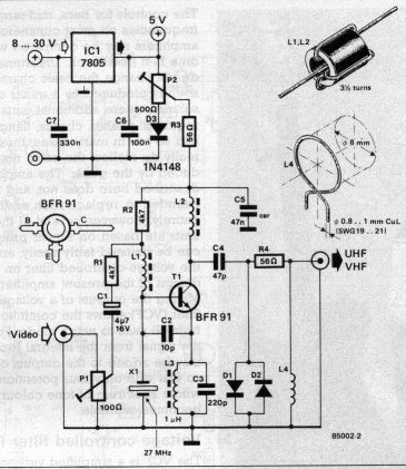 |
Parts list
Resistors: R1, R2 = 4k7 R3, R4 = 56ohm P1 = 100 ohm preset P2 = 500 ohm preset Capacitors: C1 = 4mf7/16 V C2= 10p C3 = 220p C4 = 47p C5 = 47n, ceramic C6 = 100n* C7 = 330n* Inductors: L1, L2 = 3.5 turns of 0.2 mm (SWG 35 or 36) CuL on a ferrite bead of about 3.5 x 3.5 mm L3 = 1 microH L4 = 1 turn of 0.8. . .1 mm (SWG 19...21) CuL, air wound with a diameter of 8 mm Semiconductors: D1, D2 = 1N6263 (Ambit/Cirkit) D3 = lN4148 T1 = BFR91 (Ambit/Cirkit) IC1 = 7805* Miscellaneous: X1 = crystal, 27 MHzd(3rd overtone) or other 3rd overtone crystal between 25 and 30 MHz *= not needed if the circuit is powered from a stabilised 5 V supply |
 |
Figure 3. Fortunately the printed circuit board for the modulator is only single-sided. The largecopper surface acts as a ground plain. |
pouvez vous publier le shema d une mire tv simple
RépondreSupprimer